
RIDGID / SeeSnake Standard with TruSense field guide
Make a longer inspection easy to follow.
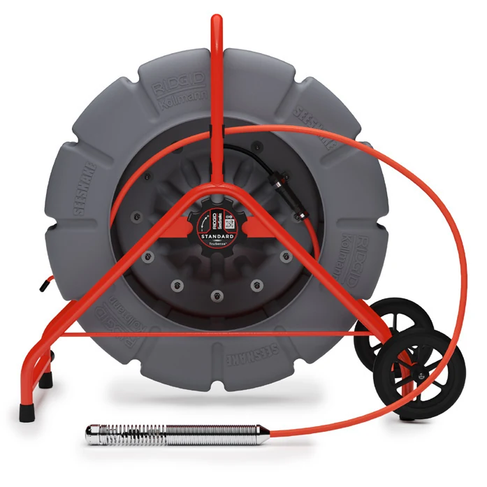
Build a stable station, manage a longer push cable and preserve the evidence from access point to final observation.
01 / Understand the task
Reach depends on the route.
A longer cable provides capacity, but turns, pipe condition and access geometry determine the usable inspection. A controlled feed and a consistent distance reference matter more than reaching the end of the reel.
Stabilize the reel
Position the frame close enough to control the feed while allowing free drum rotation. Manage the brake before advancing.
Maintain one reference
Tie the displayed cable distance to a named entrance and direction. Log any changes in the reference.
Separate viewing and locating
The video describes what the camera sees. A separate receiver locates the transmitting sonde at the stopped head.
02 / Explore the system
Follow the inspection from access to record
Select each stage to connect the setup, the observation and the record.
Support the reel and compatible monitor on stable ground. Align the cable path with the access and confirm a usable camera picture before entry.
03 / Put it to work
Know the controls. Follow the sequence.
Use the original manufacturer figures alongside the action each one supports.
Work close to the pipe entrance
The manufacturer setup keeps the feed under hand control and the display in view. The photo shows its own monitor configuration; use the controls for the monitor on your job.
Standard with TruSense manual, April 2024, PDF p.11.
1. Match the reel to the route
Confirm the actual camera-head and cable configuration, accessible entrance and likely pipe route. Inspect the frame, camera spring and cable for damage. Do not assume that full cable length is achievable through every pipe geometry. (Manual pp.7-9.)
2. Set the frame and drum
Place the unit near the entrance with room to see the monitor and guide cable by hand. Allow the drum to turn freely and set the push-cable brake appropriately. The manufacturer also shows laying the unit on its back for stability; use a secure position suitable for the work surface. If fitting wheels, follow the assembly drawing for your axle revision. (pp.9-11.)
3. Make the monitor connection
With power isolated, align the guide pin and ridge, insert the system connector straight and tighten the outer locking sleeve. Do not rotate the body. Connect and power the compatible monitor according to its own instructions; confirm the live image before pushing. (p.11.)
4. Open the job at the entrance
Select the recording destination, confirm capacity and capture a short playback check. Record the job name, access, direction and units. If using CS6x Versa, a Zero hold longer than three seconds resets system distance; a short press toggles the bracketed segment counter. Establish the origin deliberately. (CS6x Versa pp.12-15.)
5. Feed cable under control
Advance slowly while watching the picture. Keep the outside cable supported in short lengths and avoid kinks, sharp entry angles and large loops. Use suitable pipe guides when needed to center the head. Stop and reassess increased resistance; the camera is not a cleaning tool. (Standard manual p.11.)
6. Capture each observation clearly
Stop forward movement for a steady view of joints, changes in material or visible defects. Capture video and selected stills using the matched monitor controls, and connect each observation to distance and direction. Describe what is visible and identify obscured areas. Do not infer an unseen condition or convert head pitch directly into pipe grade.
7. Confirm the surface location
Stop the head at the feature, enable its 512 Hz sonde and set the separate receiver to the matching sonde mode. CS6x Versa uses its Sonde key to toggle transmission. Follow the receiver procedure to confirm position and alignment before logging depth; repeat the locate if the head moves. (CS6x Versa p.13.)
8. Close the record and recover the cable
Stop recording and wait for writing to finish; verify files before removal or delivery. Retrieve with slow, steady tension and wipe the cable as you feed short lengths back into the drum. Isolate power before cleaning and inspect the jacket again. Use gentle cleaning, never high-pressure washing. (Standard manual pp.11-13.)
04 / Inspect the result
Recognize what needs a closer look.
Use the record and the setup together when deciding what to investigate.
Choose the matched assembly drawing
The current Standard manual uses a slotted-screw and domed-endcap wheel arrangement. Earlier hardware may differ; do not combine axle procedures across revisions.
Fixed and self-leveling are options
Confirm the purchased head before describing the image behavior. TruSense is not a guarantee that every Standard kit has the same head.
Cable distance is a path measurement
The cable follows the pipe and may have slack. It is useful for referencing footage but does not replace a surface locate or a surveyed coordinate.
Drum will not feed normally
Stop pushing. Check brake engagement, reel stability and whether cable is caught outside the drum. Correct the setup before applying more force.
Distance no longer matches the job notes
Determine whether a system reset or temporary segment was used. Preserve the original notes and identify the changed reference rather than assigning earlier observations a new origin.
Image is bright but detail disappears
Stop movement, clean the accessible lens when safe and adjust the selected monitor illumination. Record that visibility is limited if water or deposits continue to obscure the pipe.
05 / Deliver with evidence
Finish with a record someone else can use.
Work through the checks before the job leaves your device.
Guide scope & manufacturer resources
Configuration and edition
For SeeSnake Standard with TruSense, not the newer Standard DSL. Camera-head and cable-length options vary. The CS6x Versa is an explicitly named controller example; no monitor or locator is implied to be included.
Current April 2024 Standard with TruSense manual is the operating source; earlier wheel-assembly instructions were not reused. Monitor controls are conditional. The imagery and procedure do not establish kit contents or DSL functionality.
Manufacturer figures retain their published example values and status messages. Use the settings and complete operating instructions for the installed configuration. Independent record and handoff checks are Drain Equipment Supply recommendations.
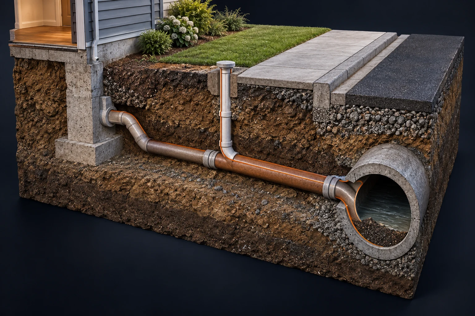
The contextual landscape is an AI-created illustration; workflow graphics are authored teaching diagrams. These visuals are not recorded inspections or measurement results.
Manufacturer references
- SeeSnake Standard with TruSense Operator Manual
Printed April 11, 2024; 999-995-131.10. PDF pages 7-13. - SeeSnake CS6x Versa Operator Manual
Printed October 7, 2024; 999-995-202.10. PDF pages 12-15; controller-specific examples only.