
RIDGID / SeeSnake Compact M40 field guide
Small footprint. A complete inspection record.
Set up the Compact M40, control the push cable and turn a pipe view into a traceable customer handoff.
01 / Understand the task
The reel sees. The monitor records.
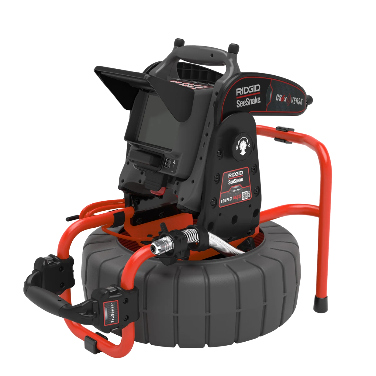
The Compact M40 carries the camera, push cable and sonde. A compatible monitor supplies the viewing and recording workflow. Establish the access point, distance reference and recording destination before the camera disappears into the pipe.

Route before pushing
All three cable guides must carry the cable. The spring clip has a temporary routing position and a separate operating position.
Keep the distance meaningful
Set the reference at the access point. A segment measurement and a full system zero are different operations on the CS6x Versa.
Locate a stationary head
Enable the 512 Hz sonde, match the receiver and stop the camera while establishing its surface position. Cable distance alone is not a surface location.
02 / Explore the system
Follow the inspection from access to record
Select each stage to connect the setup, the observation and the record.
Support the reel and compatible monitor on stable ground. Align the cable path with the access and confirm a usable camera picture before entry.
03 / Put it to work
Know the controls. Follow the sequence.
Use the original manufacturer figures alongside the action each one supports.
Spring clip: operating position
Return to this position after routing the head through the guides. The clip controls the cable during use.
Compact M40 / M40 DSL manual, June 2025, PDF p.10.
1. Establish a dry, stable station
Place the reel near the entrance where the drum can rotate freely and you can see the monitor while controlling the cable. Inspect the cable jacket, camera and connections. Keep the power arrangement dry and address damaged equipment before starting. (Reel manual pp.9-10.)
2. Route the camera through all three guides
If the head is stored inside the drum, press the spring-clip tab outward into its locked-open routing position. Bring the camera through the inner guide and both outer guides. Return the spring clip to its normal operating position before inspection. Do not leave the cable bypassing a guide. (p.10.)
3. Connect and secure the display
With power isolated, align the connector guide pin and ridge, insert straight and rotate only the outer locking sleeve. Never twist the connector body. If docking a CS6x Versa, align the docking fins and sockets and seat both locks; carry the assembly by the reel frame handle, never the monitor or kickstand. (p.11.)
4. Establish the job and distance reference
On the selected monitor, prepare the recording medium and confirm a usable live image before entering the pipe. Record the access point and units. CS6x Versa example: hold Zero for more than three seconds for system zero; a press shorter than one second toggles a temporary segment measurement shown in brackets. Do not silently reset the job origin mid-run. (CS6x Versa pp.12-15.)
5. Advance with short, controlled pushes
Keep a hand near the entrance and avoid unsupported loops. Watch the image as you advance; slow down at bends and transitions. Select suitable pipe guides to center the camera and keep the lens clearer. Stop at rising resistance; withdraw and reassess instead of using the head to dislodge material. (Reel manual p.11.)
6. Record an observation the customer can find again
Use the monitor recording controls and verify that capture has started. Pause forward movement at an observation to obtain a stable view; identify the feature, distance and direction in narration or job notes. Adjust illumination to reveal the surface rather than washing it out. Camera pitch is a head-orientation aid, not proof of pipe grade.
7. Locate the sonde at the observation
With the camera stationary, enable its 512 Hz sonde through the monitor. On a CS6x Versa, the Sonde key toggles transmission. Set the separate compatible receiver to 512 Hz sonde mode and follow its locating procedure; confirm alignment and repeatability before recording a mark or depth. Recheck after moving the camera. (CS6x Versa p.13.)
8. Save, retrieve and clean
Stop capture, finish the job and wait for storage activity to finish before removing media. Check playback. Pull the cable back slowly and steadily, wipe it as it returns and feed short lengths into the drum. Power down and isolate before cleaning. Use soft cloths, a soft nylon brush and appropriate mild cleaning products; never a pressure washer or solvents. (Reel manual pp.11,13.)
04 / Inspect the result
Recognize what needs a closer look.
Use the record and the setup together when deciding what to investigate.
A reel is not a recorder
Monitor selection determines media, job handling and exact button behavior. Verify the actual kit before preparing the workflow.
Pitch is not pipe slope
TruSense orientation describes the camera head. Bends, guides and head position can affect it; avoid turning a displayed angle into an unsupported grade measurement.
Preserve the point of reference
If a temporary counter segment is used, identify where it began. The customer should be able to follow the same access-to-observation sequence.
No image after connection
Power down and inspect connector alignment and locking sleeve engagement. Confirm monitor power and compatibility, then restart. Do not rotate the connector body or probe energized contacts.
Push cable bows outside the pipe
Stop feeding, reduce the exposed loop and reposition the reel nearer the entrance. Increasing force stores energy in the cable and does not resolve a blocked route.
Location will not repeat
Confirm sonde transmission, 512 Hz receiver mode and a stationary head. Re-establish the receiver orientation using its manual and note nearby interference. Do not report an uncertain depth as confirmed.
05 / Deliver with evidence
Finish with a record someone else can use.
Work through the checks before the job leaves your device.
Guide scope & manufacturer resources
Configuration and edition
For the non-DSL Compact M40 with TruSense. The CS6x Versa controls below apply only when that monitor is connected; use the matched monitor manual for other configurations. Product imagery shows an example with an optional monitor, not a statement of kit contents.
The current reel manual covers DSL and non-DSL variants; this guide does not assign DSL-only capability to the catalog Compact M40. CS6x Versa controls are explicitly identified because a reel does not determine recording-button behavior.
Manufacturer figures retain their published example values and status messages. Use the settings and complete operating instructions for the installed configuration. Independent record and handoff checks are Drain Equipment Supply recommendations.
The contextual landscape is an AI-created illustration; workflow graphics are authored teaching diagrams. These visuals are not recorded inspections or measurement results.
Manufacturer references
- SeeSnake Compact M40 / M40 DSL Operator Manual
Printed June 11, 2025; 999-998-438.10 REV 2. Non-DSL Compact M40 procedures used here. PDF pages 9-13. - SeeSnake CS6x Versa Operator Manual
Printed October 7, 2024; 999-995-202.10. PDF pages 12-15; controller-specific examples only. - Compact M40 original product photograph
July 1, 2019 manual p.6; photo only. Operating text follows the current manual.