
HATHORN / H12+ Command Module field guide
Set the job. Record the evidence. Verify the handoff.
Configure the correct reel, choose storage before recording and leave the customer with a video that explains what happened underground.
01 / Understand the task
A controller workflow with a deliberate start and finish.
The H12+ brings the live view, reel configuration, overlays and recording into one station. Correct reel selection establishes the counter calibration; media and microphone settings establish what the customer actually receives.

Choose the physical reel
Select the actual reel and pushrod size in Reel Size Options. A previous saved selection may not match the reel connected today.
Choose the recording destination
Set USB, HDD or both before starting. Confirm a USB drive is present when the selected destination includes it.
Match the sonde frequency
Select 512 Hz or 640 Hz in Controller Settings, then toggle transmission with the Sonde key. Match the separate receiver to that selection.
02 / Explore the system
Understand the H12+ recording chain
Select each stage to connect the setup, the observation and the record.
The H12+ is the recording command module. Match the reel, cable connection and approved power source. Select the actual reel and pushrod size in Reel Size Options so the counter uses the correct calibration.
03 / Put it to work
Know the controls. Follow the sequence.
Use the original manufacturer figures alongside the action each one supports.
Three menu destinations
Reel Size Options, Controller Settings and File Storage Options separate calibration, capture preparation and saved-media review.
H12+ manual 1.0.0-NA-EN-20250410, PDF p.8.
1. Inspect and connect the system
Prepare a stable, dry viewing station and inspect the reel, head, flex neck, cable and leads. With power isolated, connect the compatible reel and approved controller power arrangement. Keep electrical connections clear of wet work and confirm a live picture before entry. (Manual pp.6-7,17.)
2. Select the actual reel and pushrod
Open MENU / HOME, choose Reel Size Options and select the size matching the connected equipment. The manual requires this for counter calibration and says the selection persists after restart. Confirm it again when changing reels; do not assume the previous operator chose correctly. (pp.8-11.)
3. Set units, time and recording media
Open Controller Settings. Choose distance units, check the date and time and select USB, HDD or USB and HDD. Insert suitable USB storage if it is part of the destination. The illustrated settings are examples, not required values for every job. (pp.9,11,15.)
4. Identify the job and zero at the entrance
Use the keyboard overlay and infobar for the customer, location or inspection direction. Remember that visible overlay text becomes part of the recording. Check for leftover job text, then use Counter Reset at the chosen distance origin. Record where that origin is. (pp.10,12.)
5. Start capture and control the inspection
Press Video Recording and check the recording notification and selected storage. Use the MIC key to set narration deliberately: green means on and red means off in this manual. Adjust LED brightness for visible pipe detail. Push slowly, avoid flex-neck kinks and stop at resistance; leave a few turns of pushrod on the reel rather than unspooling it completely. (pp.12,15,17.)
6. Document and locate the feature
Pause forward movement for a stable view and use the screenshot key for a JPEG when useful. To locate, select the intended 512 Hz or 640 Hz sonde frequency in settings, then press Sonde to transmit; check the green active-frequency infobar. Set the separate receiver to that same frequency and follow its orientation and locating procedure with the head stationary. Repeat after moving the head. (pp.12,15,18.)
7. Stop, save and play back
Press STOP to finish the recording and wait for the save confirmation. Open MENU, File Storage Options, select the dated folder and file, and use the displayed playback options. Verify useful picture and narration before concluding the visit. Preserve a verified customer copy before deleting any source file. (pp.15-16.)
8. Recover and clean the equipment
Retrieve slowly while wiping the pushrod and avoiding kinks in the camera flex neck. Power down and isolate before cleaning. Use a soft damp cloth and clean the camera after the inspection; never use a pressure washer. Inspect damage before packing and keep contaminated equipment separated from clean work materials. (pp.17,19.)
04 / Inspect the result
Recognize what needs a closer look.
Use the record and the setup together when deciding what to investigate.
The selected reel affects the counter
Correct reel and pushrod selection is a setup prerequisite, especially when the command module moves between reels.
What is on screen can be in the file
Check old customer text and infobar entries before capture. A clean, accurate overlay makes the recording easier to interpret.
The microphone needs its own check
A moving image does not confirm narration. Read the MIC state and listen to a playback sample.
Save to the intended medium from the start
Choose USB, HDD or both before recording. This avoids depending on a post-job copy sequence to create the first customer copy.
Counter appears inconsistent
Recheck the selected reel, pushrod size and distance units. Confirm where Counter Reset was pressed, then establish and document a new reference if needed.
Video exists but narration is missing
Check the MIC state and replay a new short sample with green/on selected. Existing silent footage cannot recover audio that was never captured.
Receiver finds no reliable sonde signal
Confirm transmission is enabled and read the active frequency in the infobar. Match the receiver to 512 Hz or 640 Hz as selected, hold the camera still and repeat the receiver locating procedure. Do not infer a confirmed depth from an unstable response.
05 / Deliver with evidence
Finish with a record someone else can use.
Work through the checks before the job leaves your device.
Guide scope & manufacturer resources
Configuration and edition
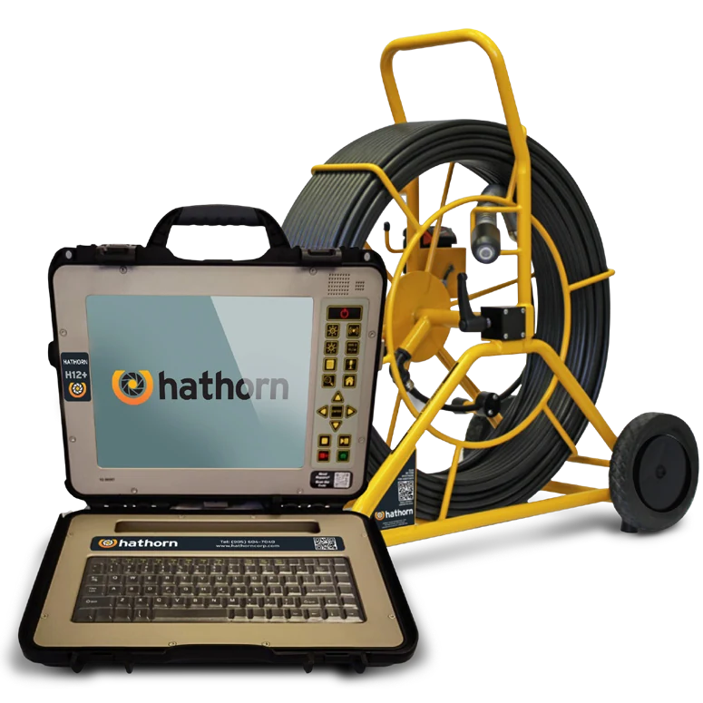
For H12+ firmware and controls described in manual 1.0.0-NA-EN-20250410. Pair with the actual compatible Hathorn reel and approved power arrangement. The product photo shows a complete example system; the command module alone does not include that reel or a locating receiver.
Control names and behavior follow H12+ manual version 1.0.0-NA-EN-20250410. The manual page 16 copy/rename paragraphs repeat deletion instructions; this guide intentionally uses destination selection before capture and verified playback, without reproducing that inconsistent sequence. The locating figure is an original manufacturer diagram, not a field photograph.
Manufacturer figures retain their published example values and status messages. Use the settings and complete operating instructions for the installed configuration. Independent record and handoff checks are Drain Equipment Supply recommendations.
The contextual landscape is an AI-created illustration; workflow graphics are authored teaching diagrams. These visuals are not recorded inspections or measurement results.
Manufacturer references
- Hathorn H12+ Controller User Manual
Version 1.0.0-NA-EN-20250410; PDF pages 8-20. - Hathorn H12+ product page
Manufacturer product and configuration reference.